
X-RAY FLUORESCENCE
X-ray fluorescence (XRF) is an analytical technique used to determine the elemental composition of materials. It is widely applied in various fields such as geology, material science, environmental analysis, and even in industrial applications for quality control.

The highlighted parts include:
X-ray Tube: This is the source that generates X-rays for exciting the atoms in the sample, causing them to emit characteristic secondary X-rays that are used for elemental analysis.
High-Voltage Generator: Supplies the necessary power to the X-ray tube, enabling the generation of high-energy X-rays for sample excitation.
Control Console: This is the user interface for operating the system, allowing control of sample loading, analysis settings, and data collection.
Automated Sample Holder: The system is equipped with an automated sample handling mechanism, where multiple sample holders are visible. This allows for high-throughput analysis, ideal for labs processing large volumes of samples.
This kind of system is typically used in laboratories for performing quantitative and qualitative elemental analysis of a wide variety of materials, commonly used in fields such as geology, metallurgy, and environmental science. The automation enhances efficiency by enabling continuous, unattended sample processing.
Course presentation for download:
How XRF Works:
- X-ray Excitation:
- The sample is bombarded with high-energy X-rays (primary X-rays) from a source, typically an X-ray tube or a radioactive source.
- When these X-rays hit the atoms in the sample, they have enough energy to knock out electrons from the inner shells of the atoms (typically the K or L shell, depending on the energy of the X-rays and the element being targeted).
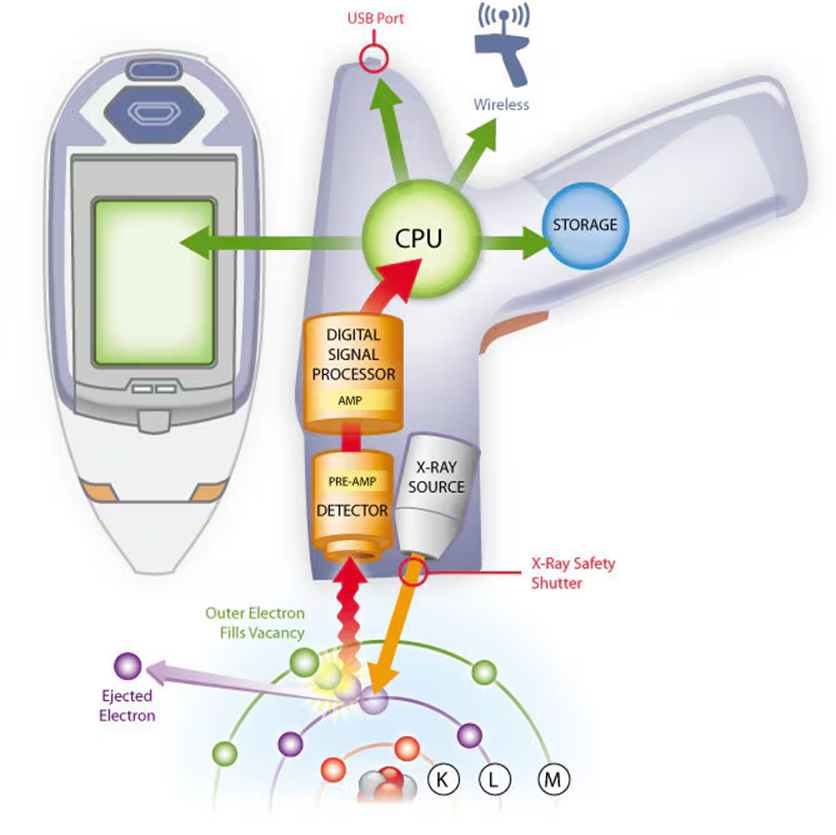
Fluorescence Emission:
- The ejection of an electron leaves the atom in an excited, unstable state.
- To stabilize, an electron from a higher energy level (outer shell) falls into the lower energy level to fill the vacancy.
- When the electron drops to a lower energy level, it releases energy in the form of secondary X-rays (fluorescent X-rays), which are characteristic of the specific element.

Detection:
- The emitted X-rays from the sample are measured using a detector, typically a silicon drift detector (SDD) or a proportional counter.
- The energy of the emitted X-rays is characteristic of specific elements, and the intensity of these X-rays correlates to the abundance of the element in the sample.

The image above shows a periodic table highlighting the range of elements typically analyzed by X-ray fluorescence (XRF) technology. The table indicates that XRF can detect elements from sodium (Na) to uranium (U), covering a wide portion of the periodic table. The concentration of these elements can range from parts per million (ppm) to high percentages, making XRF a versatile tool for both trace and major element analysis. The colour coding of the elements suggests which elements are more commonly analyzed by XRF, focusing on metals and metalloids. The excluded elements (in lighter shades) are those that are generally not detectable or are rarely analyzed by XRF due to limitations in their atomic properties, such as light elements like hydrogen, helium, and the noble gases.
Quantitative and Qualitative Analysis:
- XRF can provide both qualitative (what elements are present) and quantitative (how much of each element is present) analysis.
- The result is typically presented in terms of concentration, expressed as a percentage for major elements (see table below) or parts per million (ppm) for trace elements.

ATTENTION!!

Loss on Ignition (LOI) refers to the weight loss of a sample when it is heated to a high temperature, usually between 950°C and 1050°C. This process drives off volatile components, such as water (H₂O), carbon dioxide (CO₂), and other gases that may be present in the sample. LOI is a crucial parameter in geochemistry and material science, as it helps determine the volatile content in rocks, minerals, soils, and industrial materials like cement and ceramics.
In geological samples, high LOI values can indicate the presence of hydrated minerals, organic matter, or carbonates. In contrast, low LOI values suggest that the sample contains few volatile components. In the context of the table you shared, LOI is shown as a percentage for each sample, and it contributes to the total concentration of the sample’s composition.
Sample Preparation:
Sample preparation for X-ray fluorescence (XRF) analysis is a crucial step that ensures accurate and reproducible results. Proper preparation is necessary because XRF measures surface concentrations of elements, and uneven or inconsistent surfaces can affect the accuracy of results. Here’s a general outline of the key steps involved in preparing samples for XRF:
1. Sample Collection
- Solids (e.g., rocks, soils, minerals): These are typically crushed into smaller pieces using jaw crushers or hammer mills.
- Liquids (e.g., oils, water): Liquid samples are prepared with filters or dried into residues for analysis.
2. Grinding and Homogenization
- For solids, the material is ground into a fine powder to ensure homogeneity. A sample size reduction to around 100 µm is common to ensure a representative analysis.
- Grinding is typically done using agate, tungsten carbide, or other non-contaminating grinding media to avoid introducing foreign elements.
3. Drying
- Many geological samples, especially soils, require drying before analysis to remove moisture content.
- Samples are dried in an oven at temperatures around 105°C to avoid losing volatile elements that might be present.
4. Loss on Ignition (LOI) Determination (Optional)
- Some samples undergo LOI determination prior to XRF analysis. The sample is heated to drive off volatiles, and the weight loss is recorded. This step is often crucial in geological materials with carbonates or organic content.
5. Forming a Pellet (Pressed Pellet Method)
- The powdered sample is pressed into a pellet using a hydraulic press, often after mixing it with a binder (e.g., cellulose or boric acid). The binder holds the powder together and ensures a smooth surface for analysis.
- Pressed pellets are common for routine analysis of rock and soil samples, allowing non-destructive analysis and repeatability.
6. Fused Bead Preparation (Fusion Method)
- For some samples, particularly when higher accuracy or trace element analysis is required, the sample is fused with a flux material (often lithium tetraborate or lithium metaborate) to form a glass bead.
- This process eliminates matrix effects and enhances the accuracy for major elements by creating a homogeneous sample. The bead is then analyzed for its elemental composition using XRF.
7. Sample Mounting
- After forming a pellet or bead, it is mounted on a sample holder or stage for the XRF machine. Proper orientation and placement are crucial to avoid measurement errors.
8. Calibration Standards
- During analysis, it is important to use certified reference materials (CRM) with known compositions to calibrate the XRF instrument.
- Blanks and duplicate samples may also be prepared to verify the accuracy and precision of the XRF analysis.
Types of XRF:
- Wavelength Dispersive XRF (WDXRF):
- This type of XRF uses diffraction through crystals to separate the fluorescent X-rays by their wavelength, allowing for precise detection.
- Energy Dispersive XRF (EDXRF):
- EDXRF detects the energy of the fluorescent X-rays directly and is faster and more convenient, although slightly less precise compared to WDXRF.
Advantages of XRF:
- Rapid Analysis: Measurements are quick, often taking just a few minutes per sample.
- Versatile: It can analyze solid, liquid, and powder samples, making it useful for various materials such as rocks, metals, soils, and even archaeological artefacts.
- Portable Systems Available: Handheld XRF devices allow for in-situ measurements, making it particularly useful in field applications such as geology and mining.
Limitations of XRF:
- Surface Sensitivity: The technique primarily analyzes the surface or near-surface layers of a sample, so deeper composition may not be detected unless the sample is specifically prepared.
- Light Elements: XRF struggles to detect very light elements (like hydrogen, helium, and lithium) due to their low atomic numbers, and it can be less accurate for elements with low X-ray fluorescence energies (such as carbon, nitrogen, and oxygen).
- Matrix Effects: The composition of the surrounding material (matrix) can affect the measurement, requiring calibration and correction techniques to ensure accuracy.
Applications of XRF:
- Geology and Mineralogy: Used to determine the elemental composition of rocks, ores, and sediments. XRF can help identify mineral phases and provide data for geochemical analysis.
- Environmental Analysis: Commonly used for analyzing soils and detecting heavy metals and pollutants.
- Archaeology: For studying the elemental composition of artefacts, ceramics, and ancient materials, helping to trace origins and manufacturing techniques.
- Material Science: For quality control in manufacturing processes, particularly in industries dealing with metals, cement, and ceramics.
- Forensics: Used in criminal investigations to analyze substances or trace elements found at crime scenes.
For further details on XRF methodology watch the video below:
DETECTORS IN XRF/ELECTROM MICROPROBES
Principle of ED – XRF
The EDXRF technique relies on the following steps:
- X-ray Excitation:
- A sample is irradiated with a beam of primary X-rays, typically generated from an X-ray tube or a radioactive source.
- These high-energy X-rays excite the atoms in the sample by knocking out inner-shell electrons (usually from the K or L shells).
- Characteristic X-ray Emission:
- When an electron is ejected from an atom, it leaves a vacancy in the inner shell.
- To stabilize, an electron from a higher energy level (outer shell) drops down to fill this vacancy.
- As the electron drops to a lower energy level, it emits energy in the form of secondary X-rays. The energy of this emitted X-ray is unique to the specific element, making it possible to identify which elements are present in the sample.
- Energy Dispersive Detection:
- In EDXRF, the emitted X-rays are detected by an energy-dispersive detector, such as a silicon drift detector (SDD).
- The detector measures the energy of the incoming X-rays, and this energy is directly related to the specific elements present.
- The intensity of the X-rays at specific energy levels correlates with the concentration of the corresponding element in the sample.
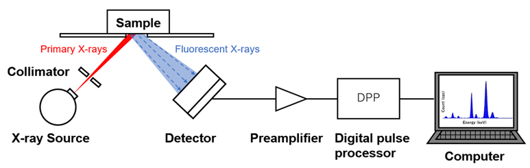
Key Components of an EDXRF System:
- X-ray Source:
- Commonly, an X-ray tube is used to generate the primary X-rays that bombard the sample. The tube produces a continuous spectrum of X-rays, and specific filters may be used to optimize the excitation for certain elements.
- Detector:
- The energy-dispersive detector (often SDD) measures the energy of each X-ray photon emitted from the sample.
- The detector produces a spectrum of the energies corresponding to different elements in the sample, allowing for identification and quantification.
- Processor and Spectrum Analysis:
- The detected X-ray energies are analyzed using a multichannel analyzer, which creates a spectrum with peaks corresponding to the energies of the detected X-rays.
- The processor analyzes the spectrum, identifying the elements present and calculating their concentrations based on the intensity of the peaks.
Advantages of EDXRF:
- Non-Destructive: EDXRF does not require sample destruction or complex preparation. This makes it suitable for analyzing valuable or sensitive materials.
- Rapid Analysis: EDXRF can provide results quickly, often in a matter of minutes, making it ideal for on-site and high-throughput analysis.
- Versatile: The technique can analyze a wide range of sample types, including solids, powders, liquids, and thin films.
- Multielemental Capability: EDXRF can detect multiple elements simultaneously, providing a full elemental profile of the sample in a single scan.
- Portable Options: Handheld EDXRF devices are available for fieldwork and in-situ analysis, making the technology highly flexible for industries like mining, archaeology, and environmental science.
Limitations of EDXRF:
- Lower Sensitivity for Light Elements: EDXRF is less effective for detecting very light elements (such as those with low atomic numbers, like hydrogen, carbon, nitrogen, and oxygen). This is because the low-energy X-rays emitted by these elements are difficult to detect.
- Resolution: EDXRF does not provide the same spectral resolution as WDXRF, which can limit its ability to differentiate between elements with overlapping X-ray energies.
- Matrix Effects: The accuracy of EDXRF can be influenced by the surrounding material or “matrix” in the sample. Matrix effects can skew the results if not properly accounted for, though modern software and calibration techniques can mitigate these effects.
Applications of EDXRF:
- Geochemistry and Mining: EDXRF is used to analyze ores, rocks, and sediments to determine their elemental composition, helping with mineral exploration and resource evaluation.
- Environmental Science: It is widely used for detecting pollutants, such as heavy metals, in soil, water, and air samples.
- Industrial Quality Control: In industries like metallurgy, cement production, and oil refining, EDXRF is employed for routine quality checks to ensure products meet the required specifications.
- Archaeology and Art Conservation: The non-destructive nature of EDXRF makes it ideal for analyzing historical artefacts, ceramics, and paintings, helping conservators understand the materials and techniques used in ancient works.
- Forensics: EDXRF is sometimes used in forensic analysis to identify and compare materials, trace elements, and other evidence found at crime scenes.
Principle of WD – XRF
Wavelength Dispersive X-ray Fluorescence (WDXRF) is an advanced X-ray fluorescence (XRF) technique used to determine the elemental composition of materials with high precision and accuracy. Like Energy Dispersive X-ray Fluorescence (EDXRF), WDXRF is based on the principle of X-ray fluorescence, but it differs in how the emitted X-rays are detected and analyzed. WDXRF uses wavelength dispersive detectors to separate the X-rays by their wavelength rather than their energy.
Here’s a more detailed look into WDXRF:
How WDXRF Works:
- X-ray Excitation:
- A sample is irradiated with a beam of primary X-rays, typically generated from an X-ray tube. The primary X-rays excite atoms in the sample by ejecting electrons from their inner electron shells.
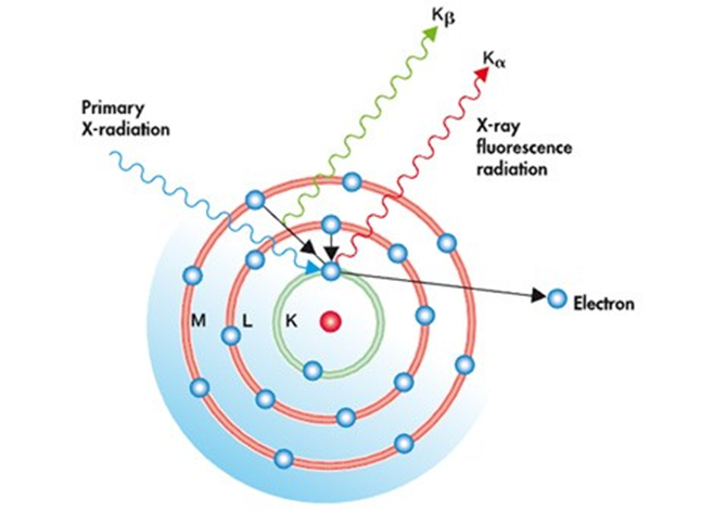
- Characteristic X-ray Emission:
- When an electron is knocked out of an inner shell (usually the K or L shell), the atom becomes unstable.
- To stabilize, an electron from a higher energy level (outer shell) drops into the lower energy level, emitting X-ray photons (secondary X-rays). The energy and wavelength of these emitted X-rays are characteristic of the element from which they originate.
- Wavelength Dispersive Detection:
- Instead of directly measuring the energy of the emitted X-rays (as in EDXRF), WDXRF uses a diffraction process to separate the X-rays by their wavelength.
- A crystal analyzer (usually made from lithium fluoride or other specific materials) is used to diffract the emitted X-rays. The crystal acts like a prism, dispersing X-rays based on their wavelength according to Bragg’s Law.
- By adjusting the angle of the crystal, X-rays of specific wavelengths can be isolated and measured one at a time.
- Detector:
- A detector (such as a gas-flow proportional counter or a scintillation counter) records the intensity of the diffracted X-rays at each specific wavelength.
- By scanning through different wavelengths and measuring their intensity, a spectrum is generated that identifies the elements present in the sample.
- The intensity of the X-rays is directly related to the concentration of the corresponding element, allowing for quantitative analysis.
Key Components of a WDXRF System:
- X-ray Tube:
- Provides the primary X-rays that bombard the sample, causing it to fluoresce.
- Analyzing Crystal:
- The crystal acts as a dispersive element, separating the emitted X-rays based on their wavelengths. Common materials for crystals include lithium fluoride (LiF), germanium, and pentaerythritol (PET).
- Goniometer:
- A precision instrument that rotates the crystal and detector to specific angles to measure X-rays of particular wavelengths.
- Detector:
- The detector records the intensity of the diffracted X-rays, providing the data needed for elemental analysis.
Advantages of WDXRF:
- High Resolution and Precision:
- WDXRF offers much better resolution than EDXRF, allowing it to distinguish between elements with very similar X-ray emissions (e.g., neighboring elements on the periodic table or elements in complex matrices).
- The technique provides highly accurate quantitative results, even for trace elements at low concentrations.
- Lower Detection Limits:
- WDXRF can detect elements at very low concentrations, making it suitable for trace-level analysis. This is particularly useful in industries where detecting impurities or contaminants is critical (e.g., semiconductor manufacturing, environmental analysis).
- Sensitivity to Light Elements:
- WDXRF can detect lighter elements (e.g., boron, carbon, nitrogen) more effectively than EDXRF, although specialized crystals and detectors are often required for this purpose.
- Reduced Matrix Effects:
- WDXRF generally handles matrix effects better than EDXRF, meaning the composition of the sample surrounding the target element has less impact on the accuracy of the results. Calibration techniques and correction methods in WDXRF are more advanced, allowing for greater precision in complex matrices.
Limitations of WDXRF:
- Slower Measurement Time:
- WDXRF is slower than EDXRF because it requires scanning through different wavelengths to detect and quantify each element separately. For applications requiring rapid analysis of multiple samples, this can be a limitation.
- More Complex and Expensive:
- WDXRF systems are more complex and expensive to operate compared to EDXRF. The goniometer, analyzing crystals, and detectors require precise control and calibration, and the instruments are often larger and less portable.
- Sample Preparation:
- In WDXRF, samples often need to be finely ground, pressed into pellets, or fused into glass beads to ensure homogeneity and reproducibility in results. This adds complexity and time to the analytical process.
Applications of WDXRF:
- Geology and Mining:
- WDXRF is used extensively to analyze rocks, minerals, ores, and soils for elemental composition. It provides high-precision measurements that are critical in resource evaluation and mineral exploration.
- Cement and Construction Materials:
- WDXRF is commonly used in the cement industry for quality control, analyzing the elemental composition of raw materials (such as limestone and clay) and the final cement product.
- Environmental Science:
- WDXRF is used to monitor soil, water, and air for pollutants, particularly trace metals and other contaminants that require highly accurate detection.
- Metals and Alloys:
- In metallurgy, WDXRF is used for quality control and material certification. It provides detailed analysis of the elemental composition of metals and alloys, ensuring they meet industry standards and specifications.
- Petroleum and Fuels:
- WDXRF is employed in the petrochemical industry to monitor sulfur content in fuels, as well as other trace elements that can impact product quality and environmental regulations.
- Glass and Ceramics:
- WDXRF is used to analyze raw materials and finished products in the glass and ceramics industries to ensure product consistency and quality.
Comparison to EDXRF:
| Feature | WDXRF | EDXRF |
|---|---|---|
| Resolution | Higher resolution and precision | Lower resolution |
| Detection Limits | Better for trace elements and low concentrations | Higher detection limits, less effective for trace elements |
| Light Element Sensitivity | Better for light elements | Less sensitive to light elements |
| Speed | Slower, as it scans each wavelength | Faster, as it detects all energies simultaneously |
| Cost | More expensive and complex | Less expensive, simpler |
| Portability | Usually large and stationary | Portable options available (handheld EDXRF devices) |
| Applications | Ideal for high-precision, laboratory-based analysis | Suitable for rapid, field-based or industrial applications |
Speed and Convenience: EDXRF is faster and easier to use since it does not require complex optics or moving parts, making it more suitable for rapid, on-the-spot analysis. WDXRF, while more precise, is slower and often used in laboratory settings for detailed analysis.
Cost: EDXRF instruments tend to be less expensive and more portable compared to WDXRF systems, which require more advanced technology for higher precision.
Summary:
X-ray fluorescence (XRF) is a powerful, non-destructive analytical tool used to determine the elemental composition of a wide variety of materials. It works by exciting atoms in a sample and measuring the characteristic X-rays they emit when returning to a lower energy state. The technique is fast, versatile, and has applications in many scientific and industrial fields, though it does have limitations regarding light elements and surface sensitivity.
Energy Dispersive X-ray Fluorescence (EDXRF) is a widely used, non-destructive technique for determining the elemental composition of various materials. It operates by exciting atoms in the sample with X-rays and detecting the energy of the emitted fluorescent X-rays to identify and quantify elements. Its speed, versatility, and capability for multi-element analysis make it invaluable across numerous industries, though it has limitations in detecting lighter elements and resolving elements with similar X-ray energies.
Wavelength Dispersive X-ray Fluorescence (WDXRF) is a precise, high-resolution technique used to determine the elemental composition of materials by separating emitted X-rays based on their wavelength. It is particularly effective for trace element detection, light element analysis, and applications that require highly accurate results. However, WDXRF systems tend to be slower, more complex, and more expensive than EDXRF, making them better suited for laboratory environments and applications where precision is critical.